
Reading Transport Stream Files in VHDL
I often find myself writing blocks of VHDL code (aka VHDL “components”) to process and manipulate MPEG transport streams. Once the component code is written, the next step is to simulate it to be sure it is functioning as intended. The usual approach is to write a “testbench” which is a further block of VHDL code that forms a “wrapper” around the component under test and feeds it with a variety of known and pre-programmed input stimuli. A VHDL simulator then allows the inputs, outputs and internal nodes of the component under test to be monitored, analysed and verified.
The testbench needs to instantiate the component under test and generate all the input signals required to thoroughly exercise it. This includes clocks, reset signals and, in the case of a component designed to manipulate a transport stream, a representative source of transport stream data.
If the function of the component under test is relatively trivial, then it is often sufficient to represent the transport stream data in a simplistic way such as a continuum of bytes where every 188th byte has the value 0x47 (the transport stream “sync” byte) and the intervening bytes are either a constant value or perhaps a rolling count. Creation of a process within the testbench to generate such data is quite straightforward.
However, for components performing more sophisticated processing of transport streams, such a simplistic approach is unsuitable and there is no substitute for using an actual captured transport stream file as the source of transport stream data. However, the testbench VHDL code required to “open and play” an actual transport stream file is not obvious especially if you are new to VHDL. The attached example testbench (testbench.vhd) shows how this is done (see process “read_ts” in particular).
Points relating to the testbench.vhd code:
The component under test is “ts_processor” declared on line 64 and instantiated on line 83. You should replace this with your own component.
The testbench presents the component under test with the following input signals:
sysclk : 27MHz system clock. Frequency is defined by the constant “SYSCLK_PERIOD” and may be changed as desired.
a_reset : An active high reset pulse lasting 5 clock periods from T = zero
ts_din : Successive transport stream bytes read from the input file
ts_syncin : High coincident with the first byte of each transport packet
ts_dvalin : Marks a clock edge for which ts_din and ts_dvalin are valid
Note that with a 27MHz frequency for sysclk, bytes will be read from the transport stream file and presented to the component under test at a rate of 27Mbyte/s = 216Mbit/s. Generally, real transport stream data will be at a lower rate than this. This is usually achieved by inserting one or more “invalid” bytes between each valid byte. For example, having each valid byte separated by an invalid byte will half the data rate to 13.5Mbyte/s. The number of invalid bytes between each valid byte is set using the integer constant N_INVALID_BYTES. For example, if N_INVALID_BYTES = 2, then every valid byte will be followed by 2 invalid bytes (i.e. signal ts_dvalin will be high for 1 clock period and then low for two clock periods) giving a TS rate of 27/3 = 9Mbyte/s. If N_INVALID_BYTES = 0, then every byte will be a valid byte (i.e. signal ts_dvalin will be permanently high) giving a TS rate of 27Mbyte/s.
Enjoy!
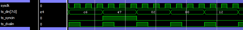
Fig 1: Input signals presented to component under test when N_INVALID_BYTES = 2

Fig 2: Input signals presented to component under test when N_INVALID_BYTES = 0
Ripcord Designs Ltd.
Ripcord Designs is a UK based electronic design consultancy. Our expertise includes optical and wireless video transmission, video and audio compression and hand-held RF camera systems.